


In this article – first presented at the 79th Conference on Glass Problems – Air Products shows us how their research team have developed a new burner technology, Cleanfire® HRx™ Burner, capable of staging nearly 100 percent of the burner oxygen while maintaining flame momentum and preserving optimal fuel/oxygen mixing. The article also presents the operational properties of the HRx burner, along with commercial demonstration results.
 |  |
Dr. Mark D. D’Agostini, Manager, Combustion Technology Development
Mr. Bill Horan, Commercial Technology Lead, Glass Applications
Air Products, Allentown, PA, USA

INTRODUCTION
Oxygen staging is a recognized technique for adjusting oxy-fuel flame properties by delaying introduction of a por-tion of the combustion oxygen into the burner flame as it discharges into the furnace. While benefits such as increased flame length and luminosity, and reduction of NOx emissions can be achieved through oxygen staging, reduction in flame momentum and inefficiencies in fuel/oxygen mixing have historically been problematic when attempting to extend the proportion of staged oxygen above about 50-70 percent of the stoichiometric oxygen requirement. Recent advance-ments in fuel and oxygen mixing control by an Air Products research team have, however, led to the development of a new burner technology, Cleanfire® HRx™, capable of staging nearly 100 percent of the burner oxygen while maintaining flame momentum and preserving optimal fuel/oxygen mixing. Results of several recent commercial installations of the HRx burner have indeed verified the ability to attain higher melting efficiency, lower NOx emissions and greater flame length control than prior art staged oxy-fuel burners, while also reducing foam formation, thereby leading to more efficient removal of glass defects in the refining section of the melter. Operational properties of the HRx burner are introduced, and commercial demonstration results are presented.

OXIDIZER STAGING BACKGROUND AND PRINCIPLES
Oxidizer staging, i.e. the delayed introduction of a portion of combustion oxidizer (air or oxygen) into a reactive fuel-oxidizer mixture, first gained widespread commercial acceptance in the 1970s and 1980s as a means of reducing NOx emissions in fossil-fuel, particularly coal-fired, power boilers. So, while this technique was known in the combustion art, by the time oxy-fuel combustion made its debut in glass melting around 1990, the top priorities for first generation oxy-fuel burners were safety and longevity. Moreover, first gen oxy-fuel melters typically led to NOx reduction exceeding 70 percent relative to air-fuel firing, so secondary NOx reduction via techniques such as oxidizer staging did not initially have a strong commercial pull. This soon changed as multiple combustion equipment and industrial gas suppliers entered the oxy-fuel burner market seeking competitive advantage.
By forcing the flame to operate sub-stoichiometrically over a substantial portion of its length, the peak flame tempera-ture becomes much lower than in a non-staged flame. This fact, and the concurrent separation of fuel nitrogen and oxygen that occurs, are the factors responsible for NOx reduction. While resultant NOx emissions are strongly influ-enced by conditions within the furnace, particularly air in-leakage, flame-to-flame interactions and batch nitrates, NOx reduction of the order of 40-50 percent between non-staged and highly staged (50 percent oxygen or greater) flames has frequently been achieved. Moreover, during early development of oxygen-staged burners for glass melting, it became apparent that benefits beyond NOx reduction were also attainable through staging. These included independent control of visible flame length, flame luminosity and biasing the direction of flame radiation. While the first of these O2-staging effects, control of visible flame length, was easy to anticipate due to the temporary oxygen deprivation of the flame, the 25-30 percent increase in visible flame length achieved by staging up to 50 percent of the combustion oxygen was nevertheless surprisingly large. The practical benefit of this feature is that it provides furnace operators a convenient means for optimizing flame shape while maintaining constant energy input to the melter.
Luminosity effects due to staging are especially evident for oxy-natural gas flames. This is so because flame luminos-ity comes principally from blackbody radiation of carbon-rich nano-
particles known as soot, and methane (principal component of natural gas) has the lowest sooting propensity of all commonly occurring hydrocarbons. Hence, any in-cremental increase in soot formed during methane combustion has a more pronounced effect on flame radiation than a comparable increase in a higher sooting fuel, such as ethane, propane or butane, for example.
Soot formation (nucleation) and growth occur at high temperature in reducing environments through the influence of soot precursors, such as benzene and acetylene, that are formed during fuel pyrolysis [1,2]. These processes, which are largely endothermic, require sufficient time at elevated temperature to overcome strong C-H bonds that stand in the way of soot formation. Hence, the greater the time spent in a strongly reducing environment prior to addition of stoi-chiometric oxygen, the more soot is likely to be formed in the flame. While we have not directly measured either the soot concentration or resultant flame emissivity, we have indeed measured radiation from oxy-fuel flames having different levels of oxygen staging. Example results are provided in Figure 1 as relative flame radiance vs wave-length. Note that the radiation spectra for a non-staged flame and one in which 70 percent of the oxygen is staged are qualitatively similar except in the range from 600 to approximately 1300 nm, which comprises parts of both the visible and near infrared regions. In this domain, where the effect of blackbody radiation coming from soot is quite prominent, radiance from the highly-staged flame is an order of magnitude higher than from its non-staged counterpart.
Absent from the above discussion, however, is the detail of how the staged oxygen is introduced into the flame. If the staged oxygen is introduced beneath the flame then, as illustrated in Figure 2, soot oxidation on the flame underside results in a highly luminous zone having an unimpeded visible path to the glass surface, and a partially obstructed up-ward path. Clearly, this has the potential for enhancing flame-to-glass heat transfer rates while simultaneously reduc-ing flame-to-crown heat transfer. We have in fact repeatedly observed the proper use of “under”-staged vs non-staged flames translate into lower crown temperatures, higher production rates, higher efficiency and/or higher glass tempera-tures; the latter of these benefits typically leading to lower rates of glass defects [see Ref. 3, for example]. Measurements on the directional biasing of flame radiation are presented in Figure 5 and are discussed in a subsequent section.
PRACTICAL CHALLENGES IN IMPLEMENTATION OF STAGING
The top priorities in all oxy-fuel burner designs is durability and particularly the avoidance of frequent maintenance and catastrophic failure, either to the burner or furnace. To this end, the potential side effects of oxygen staging must be understood. In the interest of brevity, two are mentioned herein; 1) flame licking within the burner block and 2) flame lofting.
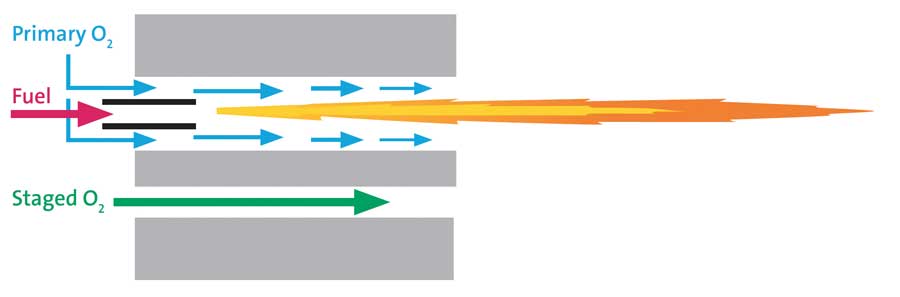
Conventional oxy-fuel burner design is of the non-premix type in which the first contact between fuel and oxygen occurs at the burner nozzle. Fuel is thus ignited at or near the ini-tial point of oxygen-fuel mixing, and the flame begins to accelerate through a “pre-combustor” channel that spans from cold face to hot face within the refractory burner block (see Figure 3). Note how a thin, annular stream of oxygen forms a separation barrier be-tween the high temperature (> 5000°F) oxy-fuel flame sheet and the refractory wall. Oxygen is, however, progressively consumed as the gases flow from nozzle to the pre-combustor discharge plane at the hot face, gradu-ally diminishing the protective barrier.
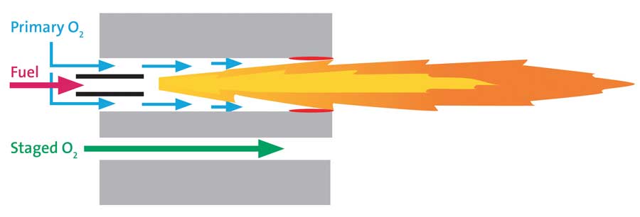
It is thereby apparent that if too much oxygen is diverted to another passage for staging purposes, a point will be reached wherein the flame begins licking the wall of the pre-combustor (see Figure 4). If this situation remains undetected/uncorrected, the burner block will eventually suffer high-temperature damage, with the risk of a catastrophic block failure that could alter tra-jectory of the oxy-fuel flame, leading to a variety of unintended consequences.
Since in a stoichiometric oxy-methane flame, the ratio of oxygen to fuel mass flow rate is 4.0, oxygen staging has the potential to substantially reduce flame momentum. Moreover, momentum transfer from the flame to the surround-ing gases occurs as the flame penetrates through the combustion space, further lowering flame momentum. So, as the flame is hotter and, hence, less dense than the surrounding furnace atmosphere, a maximum staging level is ultimately reached wherein the flame’s buoyancy overcomes its momentum, and the flame begins to turn upward toward the crown, leading to high crown temperatures and possible crown damage.
Our experience with early generation staged burners indicates that, depending upon factors such as burner firing rate and placement within the furnace, the maximum oxygen staging level after which one or both the foregoing limita-tions occur is in the 50-70 percent range, sometimes lower. That said, exploratory work carried out by our R&D team suggested that further performance benefits could be realized if these limits could be safely overcome. The results of this explor-atory effort, as summarized in the following section, culminated in the development of new burner technology with expanded staging limits and functionality.
DRIVERS FOR EXPANDING THE ROLE OF OXYGEN STAGING
Two principal factors drove our en-gineering development to overcome and expand burner oxygen staging capabilities. Firstly, as summarized in Figure 5, our laboratory data on direc-tional biasing in flame radiation from a commercial-scale oxy-fuel burner with under-flame oxygen staging indicated a substantial increase in the ratio of downward to upward flame radiation could be realized by increas-ing staging beyond the perceived maximum range of 50-70 percent. Based on the foregoing discussion, this alone should afford greater protection to the furnace crown while further increas-ing flame-to-glass heat transfer, reducing NOx and expanding flame length control.
A second, and ultimately stronger, motivation toward enabling “extreme” levels of oxygen staging is the tendency for surface foam to form in oxy-fuel melting tanks. Most investigations into the root cause of increased propensity for foaming in oxy-fuel glass furnaces focus on the higher atmospheric moisture content of oxy-fuel combustion prod-ucts (~55 vol%) vs air-fuel combustion products (~15 vol%). It has in fact been shown by several [4 – 6] researchers that the solubility of water in molten glass leads to higher equilibrium water concentration in glass produced in oxy-fuel furnaces. As it relates to foaming, water vapor displaces other fining gases, particularly SO2, leading to a higher rate of bubble formation/evolution for a fixed amount of sulfate, resulting in a higher driving force for surface foam formation, particularly in soda-lime glass.
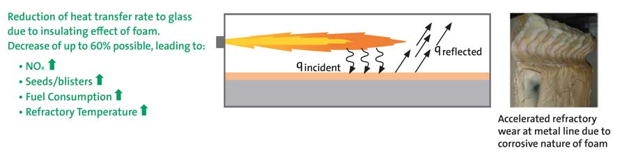
Once formed, foam acts as an insulating barrier to heat transfer between the combustion space and molten glass that reflects incident thermal energy to the crown and other walls of the melting tank. Numerous deleterious effects ensue, including crown overheating, loss of thermal energy to the flue gas, cooling of the glass leading to breakdown of sec-ondary glass flows and, consequently, reduction of molten glass residence time leading to retention of impurities and higher product defect rates. Moreover, the foam is known to be highly corrosive to most side-wall refractories and can lead to rapid loss of refractory near the metal line (see Figure 6).
Before delving further into the foam problem, it is necessary to divide glass surface foam into the following two funda-mental categories:
1. Primary Foam is formed from the release of carbon dioxide gas from batch carbonates, generally occurring in the melting zone of the furnace at temperatures between about 900 and 1300°C.
2. Secondary Foam is produced in the fining zone where it is driven through the release of sulfur dioxide from batch sulfates at temperatures above 1400°C. Importantly, the rate of gas evolution increases with increasing glass temperature.
As the presence of secondary foam generally leads to more problematic consequences to glass product quality, our dis-cussion is hereafter limited to this class of foam. Following an overview of factors leading to secondary foam formation and mitigation, our attention is fixed on techniques for foam intervention through combustion control.

Addition of sulfates to the batch is a common means of promoting the release of glass impurities in the fining zone of a glass melter. Outgassing of the sulfates at glass temperatures exceeding 1400°C produces sulfur dioxide bubbles that rise to the surface along with other dissolved gases that, if not removed, would contribute to defects in the final product. Foam formation and (relative) stability is the result of a complex and dynamic balance between gas bubble formation, rise rate and evolution versus liquid drainage from foam cells. This balance depends on coupled effects of numerous fac-tors including batch sulfate concentration, glass temperature, atmospheric moisture content, molten glass viscosity and surface tension [4-6].
Approaches to secondary foam mitigation span a variety of techniques including control of cullet quality/quantity, modification of batch sulfate concentration (or other fining agents) and introduction of surface active reagents such as sodium sulfate or sodium/potassium hydroxide [7, 8]. One further foam mitigation technique of present interest is introduction of reducing agents such as coal, coke or oil into the batch, whose effect on redox reactions in the batch and melt is believed to subsequently influence decomposition of sulfur compounds in the fining zone [9]. The method has spawned attempts at introduction of locally-reducing gaseous atmospheres adjacent to the secondary foam surface which, although operating on a different principal, has shown potential benefits toward foam reduction. Laimbock [4] and others have, for example, suggested the effect in switching from an oxidizing to a reducing gas atmosphere above the foam surface is to alter the concentration of surface active species in foam lamellae. These, in turn, introduce surface tension gradients that directly lead to accelerated liquid drainage via Marangoni flows, thereby upsetting the foam’s self-stabilizing forces and leading to diminishing or destruction of the foam layer. One key finding of the Laimbock study was that an atmosphere comprising 1 vol% carbon monoxide markedly reduced foam levels in lab experiments, whereas an atmosphere comprising 0.1 vol% carbon mo
noxide had minimal effect [4]. Elsewhere, Rough [9] in US Patent No. 3,350,185 claimed that destabilization of foam could be produced by periodically alternating the adjacent gas atmo-sphere between oxidizing and reducing, suggesting the foam de-stabilizing effect was a function of the regular pertur-bation of the glass surface tension rather than the properties of either the oxidizing or reducing equilibrium state.
EXTENDING OXYGEN STAGING LIMITS AND ATTACKING FOAM: THE CLEANFIRE® HRx BURNER
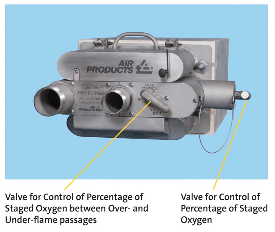
The aforementioned challenges associated with increasing staging limits, depletion of the primary oxygen “barrier” between flame and burner block pre-combustor, and loss of flame momentum, were systematically addressed and re-solved, respectively, by 1) developing a new burner nozzle that delays oxygen-fuel mixing within the pre-combustor and 2) adjusting both the overall flame momentum and the ratio of flame to oxygen staging momentum to substantially inhibit flame buoyancy. The functional improvements have led, in practice, to the routine utilization of staging levels exceeding 95 percent of the combustion oxygen without either block overheating or flame lofting. Moreover, in view of the need to address the challenge of controlling secondary foam, the new HRx burner incorporates both under-flame and over-flame staging passages (Figure 7), as well as on-burner valves (Figure 8) for convenient adjustment of oxygen stag-ing level (percent of total oxygen) and direction (under-staged, over-staged or combination of both). These added dimensions of control enable the HRx burner to be operated in one of three basic modes:
- Melt Mode: Using under-flame staging to generate a long, stable flame with luminous underside for high intensity melting
- Foam Control Mode: Using over-flame staging to maximize soot production and CO emissions beneath the flame for de-stabilizing secondary foam
- Split Mode: Using a combination of over- and under-flame staging to produce a high momentum and highly luminous flame for ensuring both flame stability and high melting efficiency in strongly turbulent environments

Adjustment of the HRx burner’s staging mode (i.e. direction) valve can be performed manually or remotely using (for example) a pneumatic actuator; the latter option being convenient if periodic switching between modes is desired.
With respect to the Foam Control mode of operation, especially in view of prior art findings emphasizing the need for substantially reducing conditions in contact with the glass surface, laboratory measurements were made of CO concen-tration approximately 2 ft beneath the flame while the burner was firing at 6 MMBTU/hr. A photo of the flame/sam-pling apparatus is provided in Figure 9, and the resultant CO concentration as a function of distance from the burner block hot face is shown in Figure 10. Note the dense concentration of soot beneath the flame and the persistently high CO concentration along the flame length, reaching a peak of approximately 10 vol% at 8 ft from the hot face. It must also be mentioned that the burner overall O2:CH4 ratio for these tests was 2.08, and that no CO was present in the exhaust gases leaving the furnace. Hence, complete mixing and reaction of the CO/unburned fuel with O2 was achieved over the latter portion of the flame (between about 10 and 16 ft from the hot face).
Beyond the added versatility due to the multiple staging modes, the enlargement of the safely attainable oxygen stag-ing percentage substantially increased the degree of independent control of flame length from roughly 25-30 percent of the non-staged length for 50 percent staging to approximately 100 percent of the non-staged length for 95 percent staging. This was all ac-complished without changing the thermal power output of the burner. Additional practical performance benefits of the new burner technology are highlighted in the following summary of commercial performance.


HIGHLIGHTS OF COMMERCIAL DEMONSTRATIONS
Performance summaries from two commercial demonstrations of the HRx burner will serve to confirm the positive effect of the enhanced operational flexibility incorporated into its design.
Demonstration 1
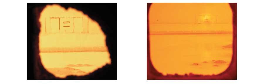
The first demonstration presented herein was at a 400 TPD, cross-fired, amber container glass furnace with incumbent Air Products’ HRi burners (maximum of 70 percent under-staging) that were entirely replaced with HRx burners. Key performance metrics established by the customer were fuel consumption, glass defects and NOx emissions. Prior to presenting results, it is instructive to visually compare the appearance of the HRi and HRx burner flames (Figure 11) to illustrate the effect of higher under-staging on flame luminosity. Note the more luminous underside to the HRx flame and the greater stratification apparent between the luminous, lower portion and the sooty, upper portion. The former aspect (luminosity increase) is responsible for delivering higher rates of flame radiation to the glass, while the latter aspect (higher concentration of soot) enables greater shielding of the crown from flame radiation. Note also that there is no lofting of the HRx flame, even though it is essentially fully staged. This confirms the effectiveness of changes in flame and staging momentum (previously mentioned) on improving flame stability.
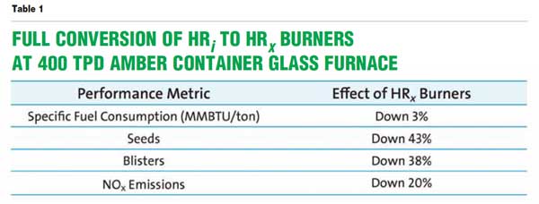
Figure 12 highlights the foam reduction afforded by the HRx burner. The burner shown in the right-hand photo (and operating in the Foam Control mode) was installed in a down-tank location where an HRi burner had been removed at an earlier date. The removal of surface foam apparent from the right-hand photo, together with the enhanced luminos-ity/radiation of the HRx Melt mode flame, were the major factors driving improved melter performance and product quality as summarized in Table 1. Note that data were averaged from several months of operation before and after the HRx installation to accurately quantify the effect of the HRx burners on melter performance.

at 400 TPD amber container glass melting furnace
Demonstration 2
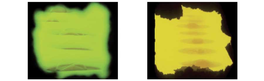
The second demonstration of the HRx burner was at a 290 TPD flint container glass furnace operating with nine HRi burners. Foam had been a historic problem at the furnace, so the customer decided to trial two HRx burners, one natural gas and one fuel oil, at the location of peak foam near the bubblers. Both burners were operated in the Foam Control mode with essentially full staging. Initial foam thickness was approximately 2 inches as depicted on the left-hand side of Figure 13. Post HRx installation, the foam was reduced by about 90 percent as is evident in the photo on the right side of the same figure. Significant modification of the down-tank furnace heat transfer distribution followed the foam reduction. As summarized in Table 2, furnace crown temperatures were reduced by 50°C, while overall fuel consumption decreases by 2.6 percent, and glass bottom temperatures remained essentially constant. This is particularly striking given that only two of nine burners were replaced and underscores the substantial thermal resistance presented by a thick foam. It may also be counter-intuitive that the crown temperature would decrease with the burner operated in the Foam Control mode, as this establishes an essentially unimpeded path between the crown and the luminous topside of the flame. This, however, is the direct result of the large reduction in reflected energy from melt surface to crown following the removal of approximately 90 percent of the foam barrier, a phenomenon we have seen occur at other installations.

SUMMARY
The review of oxygen staging in oxy-fuel glass melting burners presented herein highlights the traditional benefits and limitations, while also uncovering the potential role of staging in foam mitigation. Ensuing development efforts were successful in both increasing the practical limit on staging percentage and establishing alternative staging routes for achieving a variety of effects within the melting tank. The resultant burner technology, Cleanfire HRx, available in natu-ral gas and fuel oil versions for thermal power delivery between 1 and 12 MMBTU/hr, has proven itself to be an effective tool for increasing thermal efficiency, improving glass quality and reducing NOx emissions in industrial glass melting furnaces.
REFERENCES
1. Sidebotham, G. W., and Glassman, I.,”Flame Temperature, Fuel Structure and Fuel Concentration Effects on Soot Formation in Inverse Diffusion Flames”, Combustion and Flame, 90, pp. 269-283, 1992.
2. Leung, K. M., et al, “A Simplified Reaction Mechanism for Soot Formation in Non-Premixed Flames”, Combustion and Flame, 87, pp. 289 – 305, 1991.
3. Tyler, J. H., et al, “A Direct Comparison of Oxy-Fuel Burner Technology”, 59th Conference on Glass Problems: Ceramic Engineering and Science Proceedings (Charles H. Drummond III, Ed.), Volume 20, American Ceramic Society, 1999.
4. Laimbock, P. R., “Foaming of Glass Melts”, PhD Thesis, University of Eindhoven, ISBN 90-386-0518-8, 1998.
5. Beerkens, R., and Laimbock, P., “Foaming of Glass Melts”, Proceedings 60th Conference on Glass Problems, American Ceramic Society, 2000.
6. Kocarkova, H., “Stability of Glass Foams: Experiments at the Bubble Scale and on Vertical Film”, Unversite-Paris-Est, 2011.
7. Kim, D.S, et al, “Effect of Furnace Atmosphere on E-Glass Foaming”, Journal of Non-Crystalline Solids, 352, pp. 5287-5295, 2006.
8. Fedorov, A. G., and Pilon, L., “Glass Foams: Formation, Transport Properties, and Heat, Mass, and Radiation Transfer”, Journal of Non-Crystalline Solids, 311, pp. 154-173, 2002.
9. Rough, R. R., “Method of Eliminating a Foam Blanket on the Surface of Molten Glass, US Patent No. 3,350,185, Issued 1967.
10. Hubert, M., “Basics of Industrial Glass Melting Furnaces”, IMI-NFG Course on Processing in Glass, Lecture 3, Celsian Glass and Solar, 2015 (Available online at lehigh.edu/imi).
![]()
Air Products and Chemicals Inc.
www.airproducts.com/glass