
Page 56 - Glass Machinery Plants & Accessories no. 2-2020
P. 56
SCIENCE AND TECHNOLOGY
Science and technology
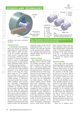
simulation and some conclusions Fig. 1 The physical model for the technological process of cold
are given. plastic deformation and work piece models
simulation stages, except for the types of active surfaces were cre-
INTRODUCTION
In present days numerical simu- mathematical model, were cross- ated: cylindrical, conical and cubic
lation has become an important checked, with particular attention spline profiled shapes, as presented
engineering tool. Numerical simu- on the physical model configura- in Fig. 1. A random roughness was
lations follow a similar procedure tion, especially with regards to the generated on the active surfaces,
to all the scientific approaches, material models and on the final as in Fig. 1. In physical model
which consist in passing through solution analysis. design, an important place must
several stages. Starting from phe- be reserved for material model
nomenon or process, the physical PHYSICAL MODEL formulation.
model is created. A mathematical The configuration of the smooth
model expresses the physical laws finishing process physical model MATERIAL MODEL
under quantitative shape with the for revolving work-pieces consid- The results from the experi-
aid of the governing equations. ered in present study, shown in mental investigations conclude that
The following stage, very impor- Fig. 1, consists in: a mandrel with most of the glass mould parts at
tant for the user of this numerical jaws, a tool with ball-shaped active Chisinau Glass Factory are made
procedure, is the discrete model part and work-piece. Tool action is of cast iron with lamellar graphite.
design. In this stage, the investi- controlled using some fictive trans- The plasticity of lamellar graph-
gator, using one of the available ducers for force measurement. The ite cast iron in the stress state in
pre-processing codes, creates an simulated working of the regime which tractions prevail is very low
adequate mesh or nodal grid in the parameters are: the machine spin- and, therefore, tensile stress must
problem domain. A well-chosen dle speed and the longitudinal be avoided in work-pieces dur-
mesh (grid) satisfies the two antag- and radial advances. During the ing the smooth finishing process.
onistic conditions: good accuracy smooth finishing process spindle Some thermal properties are also
and reasonable computational speed and, consequently, work- involved in the plastic deforma-
effort. After meshing, all problem piece speed, remain constant. The tions of metals besides mechani-
conditions are inserted and the two advancing movements are cal properties. Basic elastic-plastic
pre-processing is finished. During correlated in order to obtain the properties of the materials used
the next stage, the code solver desired profile. In all applications, in applications are distinguished
takes over the entire computational longitudinal (axial) advancing is through characteristic diagrams of
effort and provides the solution to constantly maintained, following cast iron in simple compression
the problem under numerical form. by the radial advance to be adjust- tests which were carried out at
The last stage consists in post-pro- ed according to the contact surface certified laboratories. Moreover,
cessing data, which has, as its goal, profile. To achieve the major goals Brinell and Vickers hardness tests
the completion of the solution, of numerical simulation of the were also performed at these same
additional computations and result plastic deformation technological laboratories.
analysis. In this work, all numerical process, model bodies with three Three lots of standard speci-
54 glass machinery plants & accessories 2/2020