
Page 59 - Glass Machinery Plants & Accessories no. 2-2020
P. 59
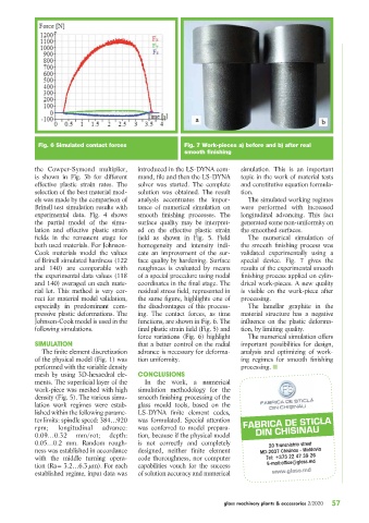
Fig. 6 Simulated contact forces                 Fig. 7 Work-pieces a) before and b) after real
                                                             smooth finishing

            the Cowper-Symond multiplier,     introduced in the LS-DYNA com-   simulation. This is an important
            is shown in Fig. 3b for different   mand, file and then the LS-DYNA   topic in the work of material tests
            effective plastic strain rates. The   solver was started. The complete   and constitutive equation formula-
            selection of the best material mod-  solution was obtained. The result   tion.
            els was made by the comparison of   analysis accentuates the impor-  The simulated working regimes
            Brinell test simulation results with   tance of numerical simulation on   were performed with increased
            experimental data. Fig. 4 shows   smooth finishing processes. The   longitudinal advancing. This fact
            the partial model of the simu-    surface quality may be interpret-  generated some non-uniformity on
            lation and effective plastic strain   ed on the effective plastic strain   the smoothed surfaces.
            fields in the remanent stage for   field as shown in Fig. 5. Field     The numerical simulation of
            both used materials. For Johnson-  homogeneity and intensity indi-  the smooth finishing process was
            Cook materials model the values   cate an improvement of the sur-  validated experimentally using a
            of Brinell simulated hardness (122   face quality by hardening. Surface   special device. Fig. 7 gives the
            and 140) are comparable with      roughness is evaluated by means   results of the experimental smooth
            the experimental data values (118   of a special procedure using nodal   finishing process applied on cylin-
            and 140) averaged on each mate-   coordinates in the final stage. The   drical work-pieces. A new quality
            rial lot. This method is very cor-  residual stress field, represented in   is visible on the work-piece after
            rect for material model validation,   the same figure, highlights one of   processing.
            especially in predominant com-    the disadvantages of this process-  The lamellar graphite in the
            pressive plastic deformations. The   ing. The contact forces, as time   material structure has a negative
            Johnson-Cook model is used in the   functions, are shown in Fig. 6. The   influence on the plastic deforma-
            following simulations.            final plastic strain field (Fig. 5) and   tion, by limiting quality.
                                              force variations (Fig. 6) highlight   The numerical simulation offers
                                              that a better control on the radial   important possibilities for design,
            SIMULATION
               The finite element discretization   advance is necessary for deforma-  analysis and optimizing of work-
            of the physical model (Fig. 1) was   tion uniformity.              ing regimes for smooth finishing
            performed with the variable density                                processing. Q
            mesh by using 3D-hexaedral ele-   CONCLUSIONS
            ments. The superficial layer of the   In the work, a numerical
            work-piece was meshed with high   simulation methodology for the
            density (Fig. 5). The various simu-  smooth finishing processing of the
            lation work regimes were estab-   glass mould tools, based on the
            lished within the following parame-  LS-DYNA finite element codes,
            ter limits: spindle speed: 384…920   was formulated. Special attention   FABRICA DE STICLA
            rpm;    longitudinal  advance:    was conferred to model prepara-       DIN CHISINAU
            0.09…0.32     mm/rot;   depth:    tion, because if the physical model
            0.05…0.2 mm. Random rough-        is not correctly and completely           20 Transnistria street
            ness was established in accordance   designed, neither finite element     MD-2037 Chisinau - Moldavia
            with the middle turning opera-    code thoroughness, nor computer          Tel: +373 22 47 39 26
            tion (Ra= 3.2…6.3 μm). For each   capabilities vouch for the success       E-mail:office@glass.md
            established regime, input data was   of solution accuracy and numerical      www.glass.md


                                                                         glass machinery plants & accessories 2/2020  57