
Page 38 - Glass Machinery Plants & Accessories no. 2-2020
P. 38
AUTOMATION AND CONTROL
Automation and control
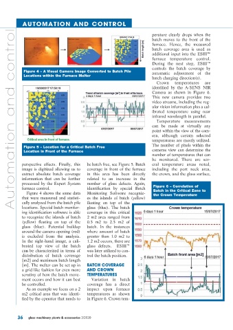
perature clearly drops when the
batch moves to the front of the
furnace. Hence, the measured
batch coverage area is used as
additional input into the ESIII™
furnace temperature control.
During the next step, ESIII™
controls the batch coverage by
Figure 4 – A Visual Camera Image Converted to Batch Pile automatic adjustment of the
Locations within the Furnace Melter
batch charging direction(s).
Crown temperatures are
identified by the A-SENS NIR
Camera as shown in Figure 6.
This new camera provides two
video streams, including the reg-
ular vision information plus a cal-
ibrated temperature using near
infrared wavelength in parallel.
Temperature measurements
can be made at virtually any
point within the view of the cam-
era, although certain selected
temperatures are mostly utilized.
The number of pixels within the
Figure 5 – Location for a Critical Batch Free
Location in Front of the Furnace cameras view can determine the
number of temperatures that can
be monitored. There are sev-
perspective effects. Finally, this be batch free, see Figure 5. Batch eral temperature areas noted,
image is digitized allowing us to coverage in front of the furnace including the port neck area,
extract absolute batch coverage in this area has been directly the crown, and the glass surface,
information that can be further related to an increase in the
processed by the Expert System number of glass defects. Again,
furnace control. identification by special Batch Figure 6 – Correlation of
Figure 4 shows the same data Monitoring Software recogniz- Batch in the Critical Zone to
that were measured and statisti- es the islands of batch (yellow) the Crown Temperature
cally analyzed from the batch pile floating on top of the
locations. Special batch monitor- glass (blue). The batch
ing identification software is able coverage in this critical
to recognize the islands of batch 2 m2 area ranged from
(yellow) floating on top of the 0.5 m2 to 2.5 m2 of
glass (blue). Potential buildup batch. In the instances
around the camera opening (red) where amount of batch
is excluded from the analysis. greater than 1.0 m2 to
In the right-hand image, a cali- 1.2 m2 occurs, there are
brated top view of the batch glass defects. ESIII™
can be characterized in terms of was later utilized to con-
distribution of batch coverage trol the batch position.
[m2] and maximum batch length
[m]. The melter can be set up in BATCH COVERAGE
a grid like fashion for even more AND CROWN
scrutiny of how the batch move- TEMPERATURES
ment occurs and how it can best Variation in batch
be controlled. coverage has a direct
As an example we focus on a 2 impact upon furnace
m2 critical area that was identi- temperatures as shown
fied by the operator that needs to in Figure 6. Crown tem-
36 glass machinery plants & accessories 2/2020